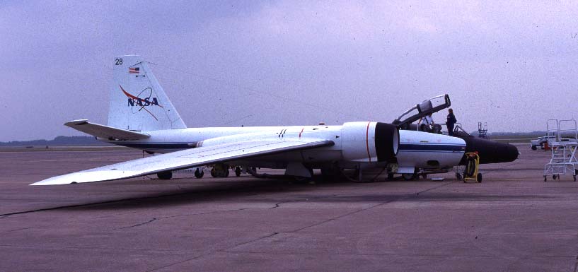
In early 1998, on the request of Dr. Martin Ross of the Aerospace Corp., we integrated an instrument to detect ClO on the NASA WB-57 aircraft at Ellington Field, Houston. The goal of this work was to quantify the emissions of reactive chlorine (Cl2, Cl2O2, ClO, and Cl) in the exhaust of launch vehicles carrying solid rocket motors, including the Titan, Atlas, and Delta rockets. In May and June we successfully detected ClO in Delta and Atlas rocket exhaust. The results will be presented at the Fall 1998 AGU meeting in San Francisco.
Our instrument, called CORE (for Chlorine Oxides
in Rocket Exhaust), was assembled from parts scavenged from
our lightweight balloon instrument that first flew in February, 1995. To
integrate CORE onto the WB-57, we had to repackage all the components into
enclosures that would meet aircraft specifications and design and build
an inlet that would sample air from beyond the boundary layer. Repackaging
represented a fairly simple engineering task, in part because we had just
completed the design and fabrication of a similar instrument for the German-built
Strato 2C aircraft (an airplane that flew successfully at 18 km, but was
later cancelled due to projected cost overruns). The inlet was much more
difficult. Earlier aircraft measurements of ClO on the NASA ER-2 were accomplished
by using a novel double-duct approach where the air is aerodynamically
decelerated from 200 m/s to about 90 m/s, and the central core is then
sampled on-axis at about 40 m/s by a second decelerating duct. This approach
was not an option on the WB-57 for RISO, because we were asked to
integrate the instrument into the fuselage (wing pods were not used for
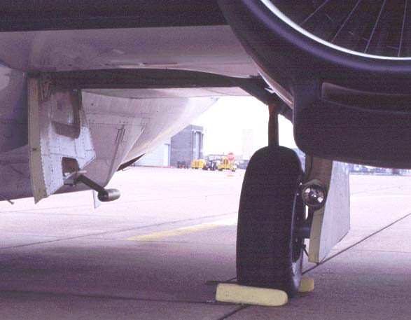
RISO). Instead, we designed a right-angle inlet that sampled air from the
center of an aerodynamic decelerator. This inlet, fabricated by Aerospace
Corp., is shown in this figure.
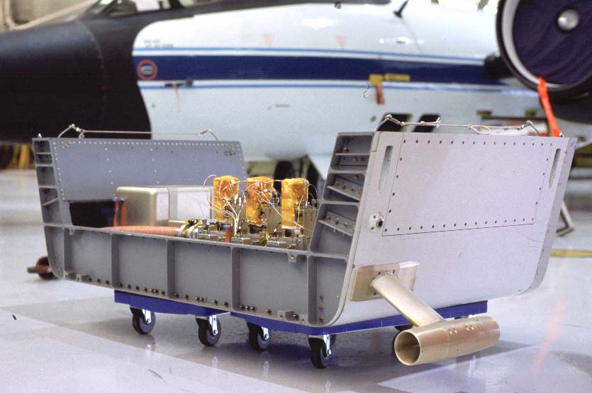 The
instrument and pallet are shown in this figure. The inlet samples from
the left side of the aircraft, from an airstream that flows between the
fuselage and the rear landing-gear door. Some instruments on the WB-57
experienced difficulties with a similar geometry. In our case, the elliptical
surfaces (based on a hybrid of designs by Fred Eisele and Paul Soderman
for measurements of radicals on other airplanes) of the 3-inch I.D. inlet
were sufficient to straighten the flow, even with the landing gear deployed.
Clearly visible in this photo are the three photomultiplier tubes, wrapped
with Nomex insulation. Due to a cooling capacity of 1000 watts from the
flow of ambient air through the instrument, the detectors had to be agressively
temperature controlled throughout the flight. In several early flights,
the detectors cooled to below 230 K, causing the electronics to fail. For
subsequent flights, they were warmed to ~10 C, where they performed reasonably
well. Also visible in this photo is the top of the 2-inch I.D. flexible
silicone tubing that was used to exhaust the flow out the right side of
the pallet.
The
instrument and pallet are shown in this figure. The inlet samples from
the left side of the aircraft, from an airstream that flows between the
fuselage and the rear landing-gear door. Some instruments on the WB-57
experienced difficulties with a similar geometry. In our case, the elliptical
surfaces (based on a hybrid of designs by Fred Eisele and Paul Soderman
for measurements of radicals on other airplanes) of the 3-inch I.D. inlet
were sufficient to straighten the flow, even with the landing gear deployed.
Clearly visible in this photo are the three photomultiplier tubes, wrapped
with Nomex insulation. Due to a cooling capacity of 1000 watts from the
flow of ambient air through the instrument, the detectors had to be agressively
temperature controlled throughout the flight. In several early flights,
the detectors cooled to below 230 K, causing the electronics to fail. For
subsequent flights, they were warmed to ~10 C, where they performed reasonably
well. Also visible in this photo is the top of the 2-inch I.D. flexible
silicone tubing that was used to exhaust the flow out the right side of
the pallet.
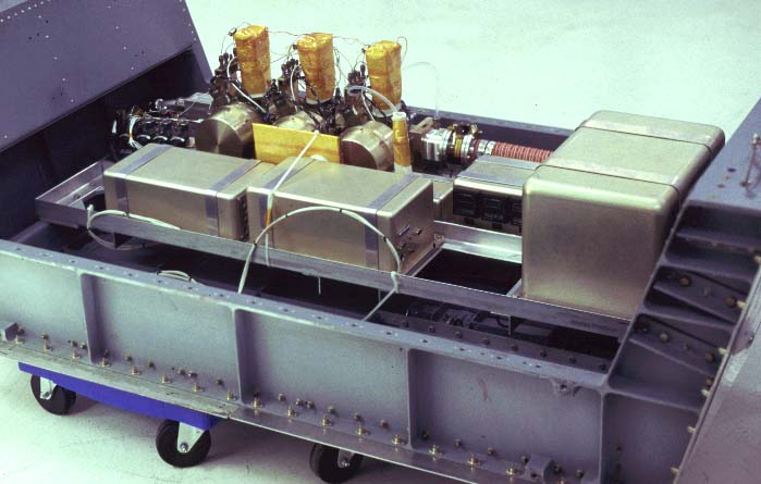 This
photo shows the complete CORE instrument as it was configured for the RISO
and WAM flights. The large box at the right encloses the gas bottles used
to store dry air (for purging optics and for use as an optical filter to
isolate chlorine atom emission at 119 nm). The two enclosures at the bottom
left are the 1500 watt power supply (300 watts are all that are needed
for this configuration of the instrument) and the data acquisition system.
For the first series of flights, we used a Ampro Littleboard 386-SX. Together
with data acquisition boards designed by Tom Thompson of the Aeronomy Lab
in Boulder, CO, we were able to sample within the plume at 1 Hz. For the
second set of plume crossings, we replaced the 386 with a faster 486-DX2
motherboard, and we were able to sample at 5 Hz. This provided over 1400
individual samples within the Atlas II plume. This computer will be replaced
by a Pentium MMX for the next round of flights in 1999 to allow for 25
Hz sampling. This will provide a spatial resolution of less than 10 meters
within the plume!
This
photo shows the complete CORE instrument as it was configured for the RISO
and WAM flights. The large box at the right encloses the gas bottles used
to store dry air (for purging optics and for use as an optical filter to
isolate chlorine atom emission at 119 nm). The two enclosures at the bottom
left are the 1500 watt power supply (300 watts are all that are needed
for this configuration of the instrument) and the data acquisition system.
For the first series of flights, we used a Ampro Littleboard 386-SX. Together
with data acquisition boards designed by Tom Thompson of the Aeronomy Lab
in Boulder, CO, we were able to sample within the plume at 1 Hz. For the
second set of plume crossings, we replaced the 386 with a faster 486-DX2
motherboard, and we were able to sample at 5 Hz. This provided over 1400
individual samples within the Atlas II plume. This computer will be replaced
by a Pentium MMX for the next round of flights in 1999 to allow for 25
Hz sampling. This will provide a spatial resolution of less than 10 meters
within the plume!
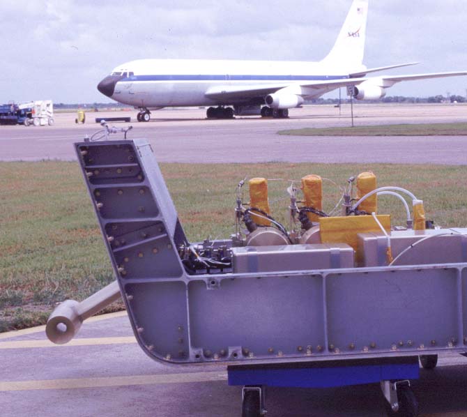 This
is the view from the rear of the pallet. The NASA KC-135, used for "zero
gravity" studies (and to film scenes of weightlessness in "Apollo 13")
appears in the background. This photo illustrates the constained geometry
that we were forced to use in order to minimize the distance between the
inlet and the detector. This was necessary to reduce loss of ClO on surfaces.
We convert ClO to chlorine atoms by adding nitric oxide to the flow within
a few milliseconds of the right-angle bend in the inlet.
This
is the view from the rear of the pallet. The NASA KC-135, used for "zero
gravity" studies (and to film scenes of weightlessness in "Apollo 13")
appears in the background. This photo illustrates the constained geometry
that we were forced to use in order to minimize the distance between the
inlet and the detector. This was necessary to reduce loss of ClO on surfaces.
We convert ClO to chlorine atoms by adding nitric oxide to the flow within
a few milliseconds of the right-angle bend in the inlet.